'Cold Air' on a 2G: 2 Approaches |
|||
| Second Approach below. | |||
| First
Approach:
Conical air filter elements offer significant gains. There is a possible catch, though. Once the airbox has been removed, the air filter can draw hot air from the engine compartment instead of cool air through the front quarter panel (like it's supposed to). First you should remove all the plastic horns in the quarter panel that may restrict the flow of air. Some people also design 'ram air' systems that have a pipe or tube that collects air where the side mount intercooler was and 'shoves' it up through the hole to the filter. This page simply shows a simple isolation panel for keeping the hot engine air away from the filter. |
|||
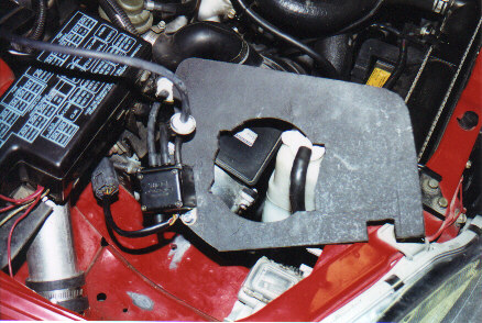 |
Using particle board or a hard (temperature resistant) plastic, you can cut trace out and cut a pattern similar to the one shown. The filter and MAS will hold the plate in place, along with a notch that rides on a little bar that's present (2G). I also attached my boost controller solenoid to this partition. | ||
| The plate slips over the adapter for the DIS filter and then the filter is installed and holds the plate in place. For additional sealing from the engine compartment, the top of the partition could be lined with rubber to fit snug against the hood. This modification should definitely help the filter to draw cooler air, as well as hold it in place. A special thanks to John Auxier for doing most of the design. | 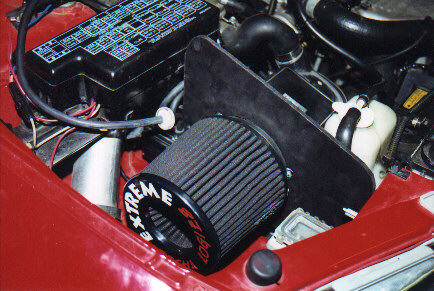 |
||
| Updated! 9/17/02 | |||
|
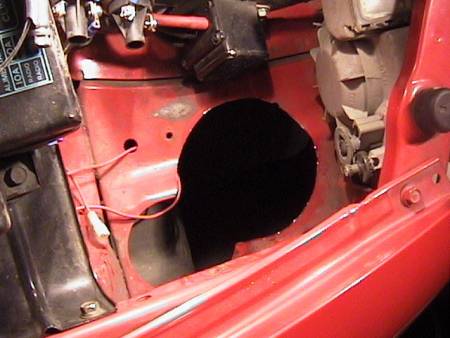
Here's another approach. This approach should draw in even more fresh air, but it does require cutting metal and the filter will get dirty more often. Parts: I used a 4.0" ID rubber elbow from a hardware store, along with a piece of PVC that fit snugly inside of it. This happens to fit over the DIS adapter bracket (it's 4.5" ID at the joiner). I also got a piece of polycarbonate plastic from a plastic supply store. First, I took the PVC pipe and outlined its size on a piece of cardboard. I cut out the cardboard and drew a circle on the appropriate part of the intake area. (Determine the appropriate area by placing the elbow where you think it will go). I used a Dremmel and a high strength cutting wheel to cut out the metal as seen. |
 |
||
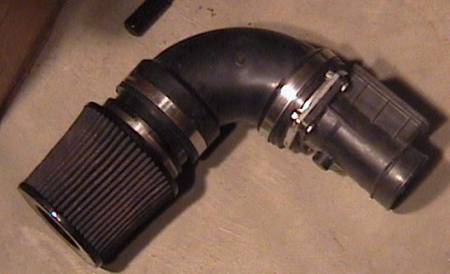 |
I trimmed the MAS side of the elbow because the tolerances were close and the joining area was more than thick enough. There is a 4" or so section of the PVC (or was it ABS? I don't remember) piping in between the filter and the elbow. The hole is size such that the elbow rests on the metal, and the pipe inside goes down through. The filter is positioned nice and high to prevent puddle problems, though you could mount it lower if you wished. | ||
| Using a jigsaw, I cut the plastic to form a nice fit as a divider. As above, this helps block hot air, and acts as a support for the piping. Do this slowly and iteratively to get the best shape. | 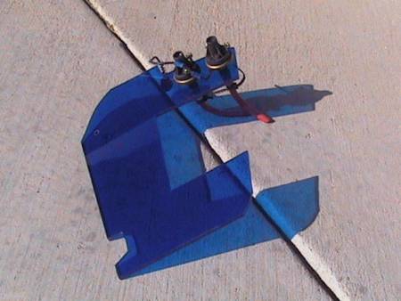 |
||
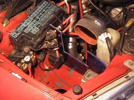 |
Here is the intake area with the
divider in place. It pushes against the fuse box and is nestled in
between two nubs on the light assembly to keep it from moving. You
can also see my boost controller solenoid mounted to the divider, as well
as Hobbs pressure switches for my water injection system.
|
||
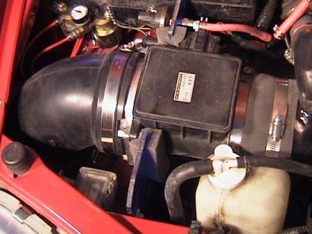
| Here is everything
installed. Snug and secure.
I lined the divider with air conditioner sealing strip to help support the MAS and to further insolate. My next step will be creating a "box" in the fender well to insolate the area from hot "under car" air. |
 |
||
| Return to the Eclipse Page. | Go to the Water Injection page. | ||